Doublers
Splice and Doubler Comparison
William F. McCombs, James C. McQueen, Jeffrey L. Perry
AFFDL-TR-67-184
Analytical Design Methods for Aircraft Structural Joints page 42
Splice Load Distribution
A splice’s function is to transfer a given load. It is kept as short as possible in accomplishing this.
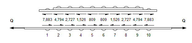
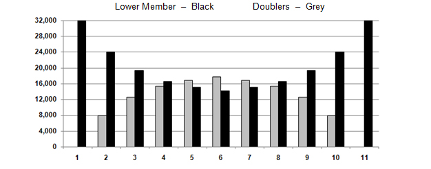
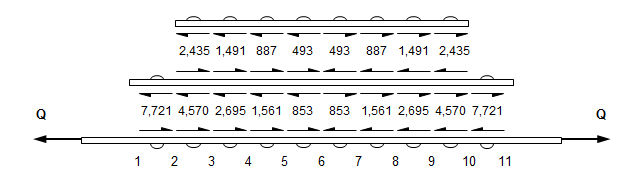
 Doubler Load Distribution
A doubler’s function is to pick up load (and relieve another member). In order to do this efficiently it must have some considerable length, although this is kept to a minimum. Therefore doublers are, by nature, relatively long members compared to splices.
Doubler Load Distribution
A doubler’s function is to pick up load (and relieve another member). In order to do this efficiently it must have some considerable length, although this is kept to a minimum. Therefore doublers are, by nature, relatively long members compared to splices.
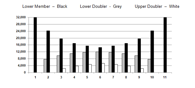
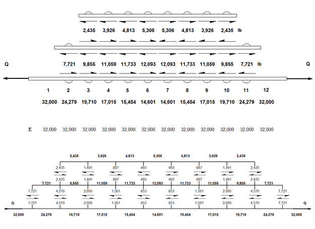
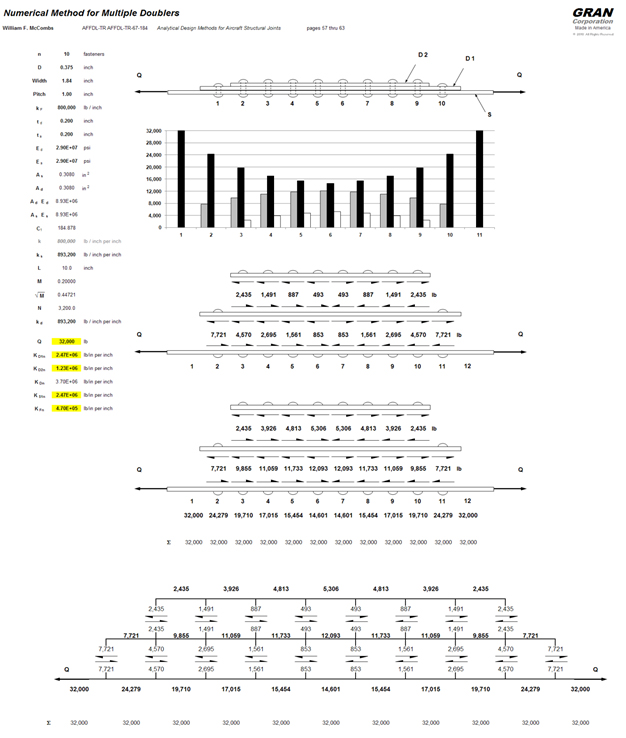
 Multiple Doublers
William F. McCombs, James C. McQueen, Jeffrey L. Perry
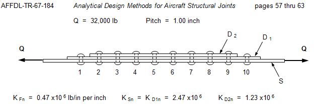
See page 59:
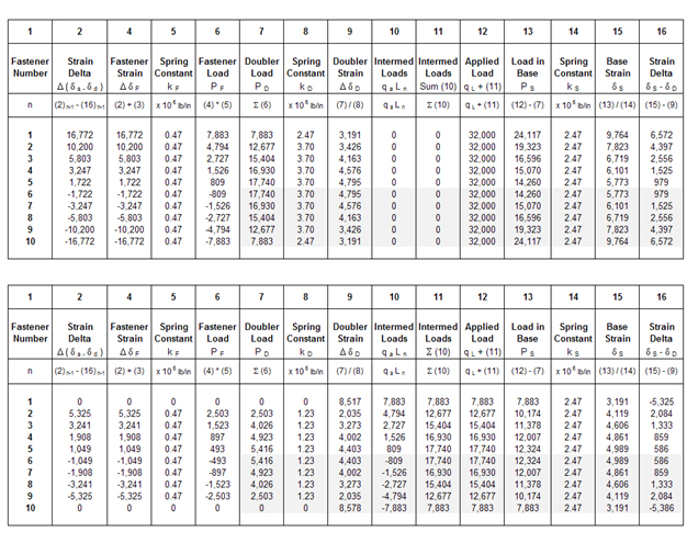
- Combine the stacked doublers D 1 and D 2 into one member, D , (by adding the k values) as in Figure III.13c. This assumes the fasteners between them to be rigid.
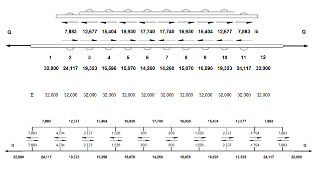
- Determine the corresponding fastener loads between this assumed member, D 1 , and the base structure, S, in the conventional tabular manner. Note the strains, Column 9 of the table.
- Then consider only the two doublers, as they actually exist, to be a structure subjected to the loads of (b) above, applied to the member D 1 , as in Figure III.13d.
- Determine the internal loads for this configuration and loading and also note the strains in the member D 1 Column 15 of the table. Member D 1 is the "base structure" in this analysis.
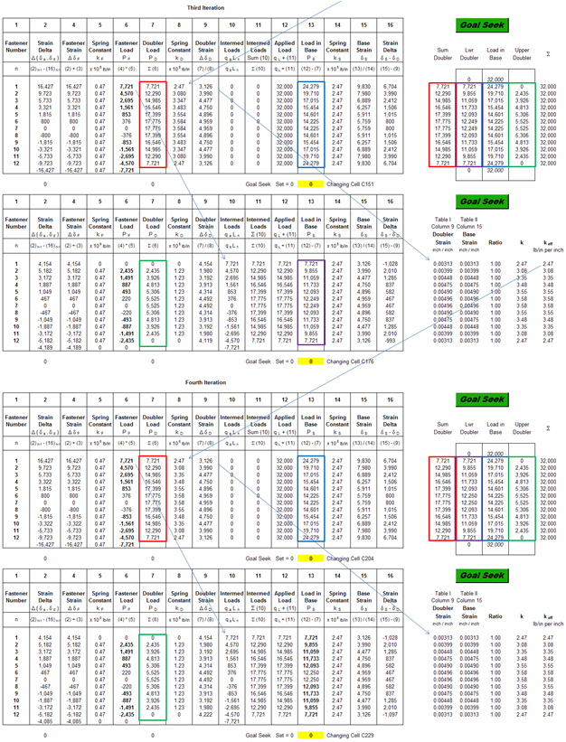
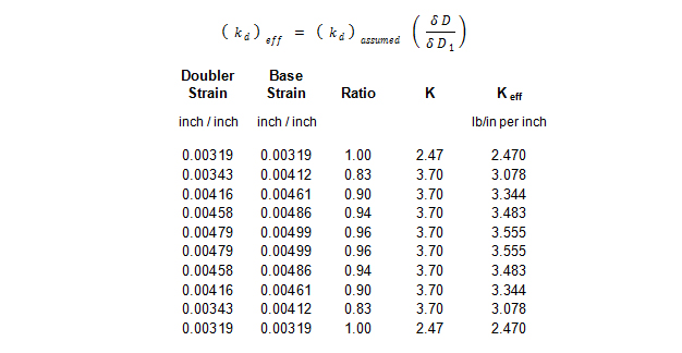
- Calculate an effective k D value for the combined members D 1 and D 2 using the member strains from (b) and (d) above is follows:
For any segment the effective k D of the combined members is taken as

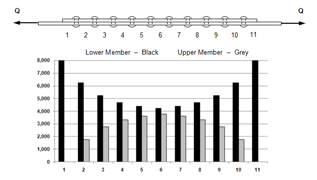
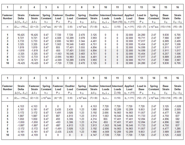
Repeat steps (b) through (e) until the doubler strains equal the base strains.
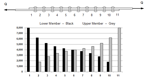
A rougher estimate can, of course, be obtained simply by carrying out steps (a) and (b) only one time. This assumes the doublers to be one integral member ard therefore results in the fastener loads and the doubler load being larger than they actually are.
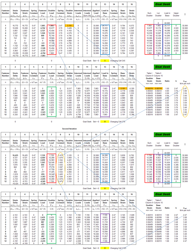
First Iteration
 Strain and Effective Stiffness
Compare the doubler strains from Column 9 in the first table to base strains in Column 15 of the second table. Use the effective stiffness you calculate in the first iteration for the second calculation and so on.
 Second Iteration
 Strain and Effective Stiffness
 Third Iteration
 Strain and Effective Stiffness
 Case I - Free Body Diagram
 Load Distribution
 Case II - Free Body Diagram
 Load Distribution
 Case I – Load Distribution
 Case II – Load Distribution
 Numerical Method
William F. McCombs, James C. McQueen, Jeffrey L. Perry
AFFDL-TR-67-184
Analytical Design Methods for Aircraft Structural Joints
William F. McCombs, James C. McQueen, Jeffrey L. Perry
AFFDL-TR-67-184
Analytical Design Methods for Aircraft Structural Joints